
Abstract
-
Latch that has one set input to store a single Bit, and another reset input to reset the stored bit
-
Active Set: turn on the output
-
Inactive Reset: locking the state of the set input when set goes inactive
-
Active Reset: turn off the output
-
Inactive Set: locking the state of the reset input when the reset goes inactive
Circuit 1
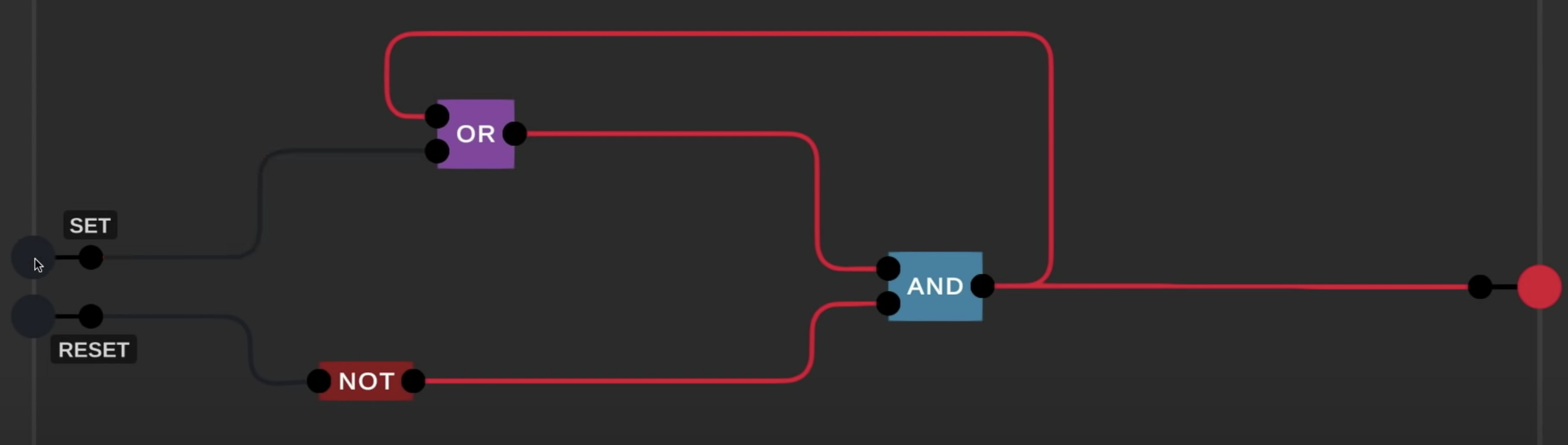
- As shown in the diagram above, we can build it with one OR, one NOT and one AND
- Refer to footnote for a nice visualisation on how it works1
Circuit 2
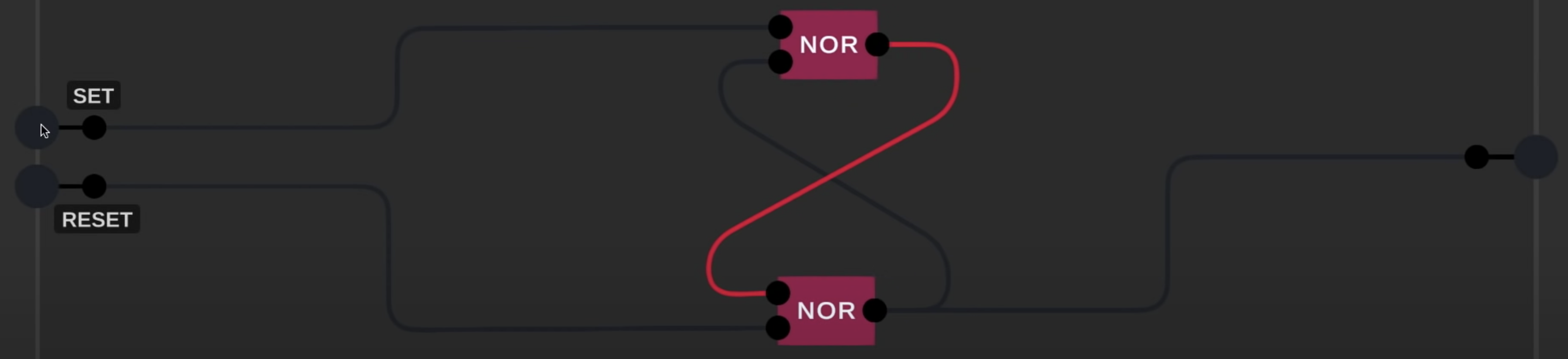
What is the output when latch first turned on without any inputs?
In an ideal case, the output will be switching from on to off in super short interval
However, in the real world, even the same two gates with the same wire will have a slightly different Gate Delay. Sometimes, one gate may have a shorter gate delay than another
Thus, the output can be
0or1when the latch is first turned onRefer to footnote for a nice visualisation of how it works3
Circuit Diagram & Truth Table
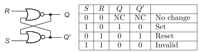
Qis the 1 bit storage
Invalid condition exists and must be avoided
- When both S & R are 1, both
Q&Q'will be 0
The Abstracted Diagram
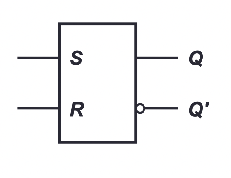
Gated S-R Latch

- Set Reset Latch with Steering Gate
- Only active when
ENis high